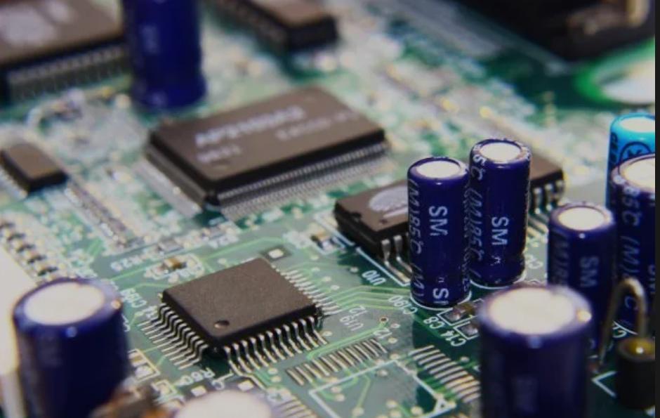
All kinds of electronic products have PCB inside to realize their function.
Electronic products will produce heat during operation, which will affect the service life of PCB.
The better the cooling design of the PCB, the longer the service life of the electronic products will be.
We will introduce the principle and method of PCB heat dissipation design in detail.
In this passage, you will learn:
1. The importance of pcb thermal design
2. PCB heat dissipation design guide
3. Temperature rising factor analysis of printed circuit board
4. PCB heat dissipation methods
The importance of pcb thermal design
In PCB design, whether it is layout or wiring, engineers should consider and meet the requirements of PCB thermal design. The heat generated by the electronic equipment causes the internal temperature to rise rapidly. If the heat is not dissipated in time, the equipment will continue to heat up and the device will fail due to overheating. Therefore, the research on pcb thermal design is very important. At present, there are also special pcb heat dissipation techniques.
PCB thermal design requirements
The first pcb thermal design requirement is about the layout of components. When arranging components, temperature sensitive components other than temperature detection components should be placed close to the air inlet, and upstream of the air duct of components with high power and high heat, and as far away as possible from components with high heat.
The second requirement of pcb thermal design is to align the vents as far as possible to devices with high heat dissipation requirements.
The third requirement of pcb thermal design is to place high devices behind low ones, and arrange the long direction along the direction with the least wind resistance to prevent the air duct from being blocked.
PCB heat dissipation design guide
Whether it is using power electronic equipment or designing a new motherboard, it is necessary to deal with the temperature rise in the system. Continuous high temperature operation will shorten the life of the circuit board, and may even cause some key points of the system to malfunction. When PCB thermal design, PCB heat dissipation should be considered as early as possible, which helps to extend the service life of circuit boards and components.
The pcb heat dissipation design starts from estimating the working temperature
Before starting pcb thermal design, you need to consider the operating temperature of the circuit board, the working environment and the power consumption of the components. These factors work together to determine the operating temperature of the circuit board and components. This will also help to customize PCB heat dissipation strategies.
Before deciding on pcb heat dissipation methods, be sure to check the allowable operating temperature of the components in the data sheet and the specified temperature in important industry standards. It is necessary to combine active and passive cooling with the correct circuit board layout in order to prevent damage to the circuit board.
Evaluate the component power
This step will estimate each major heating component used in the design and the approximate size of these packages. These packages can then be described as surface area heat sources in the simulation, with the rest of the heat being uniformly transferred to the PCB board surface.
Active cooling and passive cooling: which one is right for your circuit board?
This is an important issue that any designer should consider. Generally, when the ambient temperature is much lower than the operating temperature, the passive cooling effect is the best. The thermal gradient between the system and the environment will be large, forcing a large thermal design current to radiate from your components and the circuit board itself. Using active cooling, even if the ambient temperature is high, it can provide a better cooling effect according to the active cooling system.
Passive cooling
You should try to minimize the passive cooling of active components so that the pcb thermal can be distributed to the ground plane. Many active components include thermal pads on the bottom of the package, allowing heat to be dissipated through stitched vias to nearby ground planes. These stitched vias then extend all the way to the copper pad under the component. There are some PCB calculators that can be used to estimate the size of the copper pad required under the component.
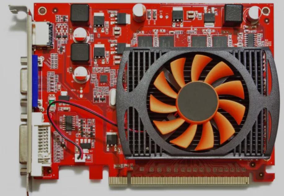
Active cooling
If you need to further reduce the pcb temperature, when passive cooling cannot solve the problem, you may need to use a fan for active cooling. The fan does not run at full speed all the time, and sometimes it may not even turn on. Components with higher temperatures and components that generate more heat require fans to run at faster speeds.
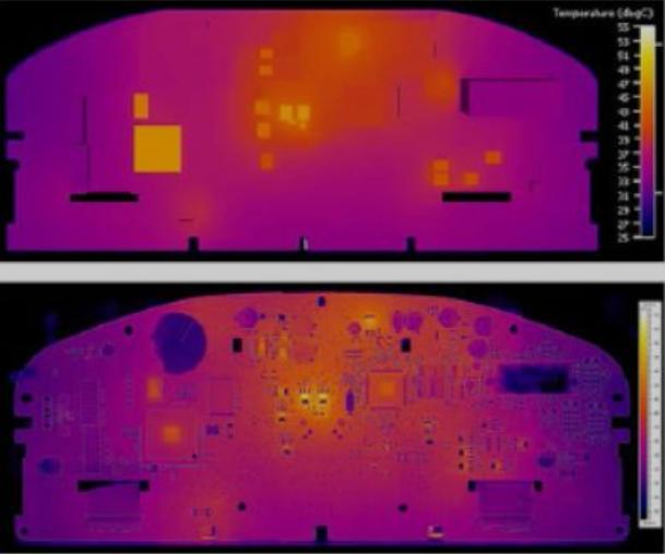
Temperature rising factor analysis of printed circuit board
The direct cause of the temperature rise of the printed circuit board is the existence of power consumption devices in the circuit. The power consumption of electronic devices varies to varying degrees, and the heating intensity varies with the tdp thermal design power.
Two phenomena of temperature rise in printed circuit boards:
a.local temperature rise or considerable area temperature rise;
b. Short-term or long-term temperature rise.
In the analysis of PCB thermal design power consumption, it is generally analyzed from the following aspects:
(1) Electrical power consumption
a. Analyze pcb thermal design power consumption per unit area
b. Analyze the distribution of pcb thermal design power consumption
(2) Structure of printed circuit boards
a. Size of the printed circuit board
b. Materials of the printed circuit board
(3) Installation method of the printed circuit board
a. Installation method (such as vertical installation, horizontal installation);
b. the sealing condition and the distance from the enclosure.
PCB heat dissipation methods
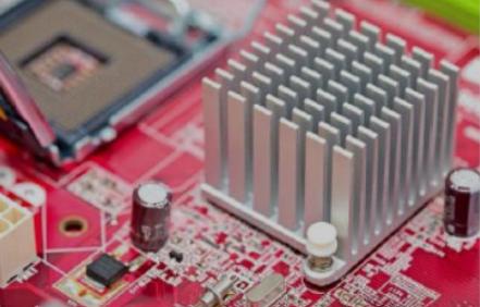
Adding the cooling fans and heat conduction PCB for high heating components
The first pcb heat dissipation method is to add a cooling fan and a thermally conductive PCB. When a few components in the PCB heat are significant (less than 3), you can add a cooling fan or heat conduction tube on the heating parts to enhance the pcb heat dissipation effect. When the heating component is more (more than 3), a large heat sink can be used. It is a particular radiator customized according to the position and height of the heating components on the PCB board or a large flat radiator to cut out different parts. The heat sink is buckled on the component surface as a whole and dissipates heat by contact with each component. However, due to the poor consistency between high and low during the assembly and soldering of parts, the heat dissipation effect is not good. Usually, soft thermal phase change pads are added to the surface of the components to improve the heat dissipation effect.
Heat dissipation through PCB board itself
The second pcb heat dissipation method is heat dissipation through PCB board itself. At present, the widely used PCB is copper-clad/epoxy glass cloth substrate or phenolic resin glass cloth substrate; there is a small amount of paper-based copper clad substrate. Although these substrates have excellent electrical properties and processing properties, they have poor heat dissipation. As a heat dissipation way for high heating components, heat dissipation can hardly be expected from PCB itself but from the surface of members to the surrounding air. However, as electronic products have entered the era of components miniaturization, high-density installation, and high-thermal assembly, it is not enough to dissipate heat only on the surface of members with a minimal surface area. They need pcb heat dissipation techniques to achieve heat dissipation.
Adopt reasonable routing design to realize pcb heat dissipation
The third pcb heat dissipation method is to use a reasonable wiring design. Due to the poor thermal conductivity of the resin in the PCB, and the copper foil wires and holes are good conductors of heat, improving the residual rate of copper foil and increasing the heat conduction holes are the main pcb heat dissipation method.To evaluate the heat dissipation ability of PCB, it is necessary to calculate the equivalent thermal conductivity of insulation substrate for PCB, a composite material composed of various materials with different thermal conductivity.
Arranged according to the degree of heat generation and heat dissipation
The fourth pcb heat dissipation method is arranged according to the degree of heat generation and heat dissipation. The parts with low calorific value or poor heat resistance (such as small-signal transistors, small-scale integrated circuits, electrolytic capacitors, etc.) should be placed at the top of the cooling airflow. Parts with high heat or good heat resistance (such as power transistors, large-scale integrated circuits, etc.) are placed in the most downstream of the cooling flow.
Placement location
The fifth pcb heat dissipation method is Placement location. In the horizontal direction, the high-power components are arranged as close to the edge of the PCB as possible to shorten the heat transfer path. In the vertical direction, the high-power components are placed as close to the top of the printed circuit board as possible to reduce the impact of these components on the temperature of other parts while working.
Temperature-sensitive components are best placed in the lowest temperature area (such as the bottom of the equipment), do not put it directly above the heating parts; multiple components are best in the horizontal plane staggered layout.
The components with the highest power consumption and maximum heat dissipation are arranged near the optimal location for heat dissipation. Do not place highly heated devices at the corners and edges of the PCB unless there is a radiator located near it.
Airflow path
The sixth pcb heat dissipation method is to study the Airflow path. The heat dissipation of the printed circuit board in the equipment mainly depends on the airflow, so the airflow path should be studied in the PCB design. The components or printed circuit board should be reasonably configured. Airflow always tends to flow in places with slight resistance, so when configuring components on printed circuit boards, it is necessary to avoid leaving large airspace in a particular area. The configuration of multiple printed circuit boards in the machine should also pay attention to the same problem.
Reduce thermal resistance
The seventh pcb heat dissipation method is Reduce thermal resistance. The thermal resistance between high heat dissipation components and PCB base material should be minimized as much as possible. In order to better meet the requirements of thermal characteristics, some heat-conducting materials (such as coating a layer of heat-conducting silica gel) can be used on the bottom surface of the chip, and a certain contact area can be maintained for component heat dissipation.
Conclusion
At present, Flotherm is the mainstream software for board-level thermal simulation analysis. Through thermal simulation analysis, thermal design can be tested, design defects can be found, and the applicability and effectiveness of the scheme can be evaluated. And PCB thermal design optimization is also a continuous iterative process. Through the design, simulation, and test cycle, the thermal simulation model is modified and accumulated, the speed of thermal simulation is accelerated, the accuracy of the thermal simulation is improved, and the PCB thermal design experience is supplemented.